


Connect sensors and protect your data logger from electrostatic discharge with an NRG wiring panel.
DETAILS
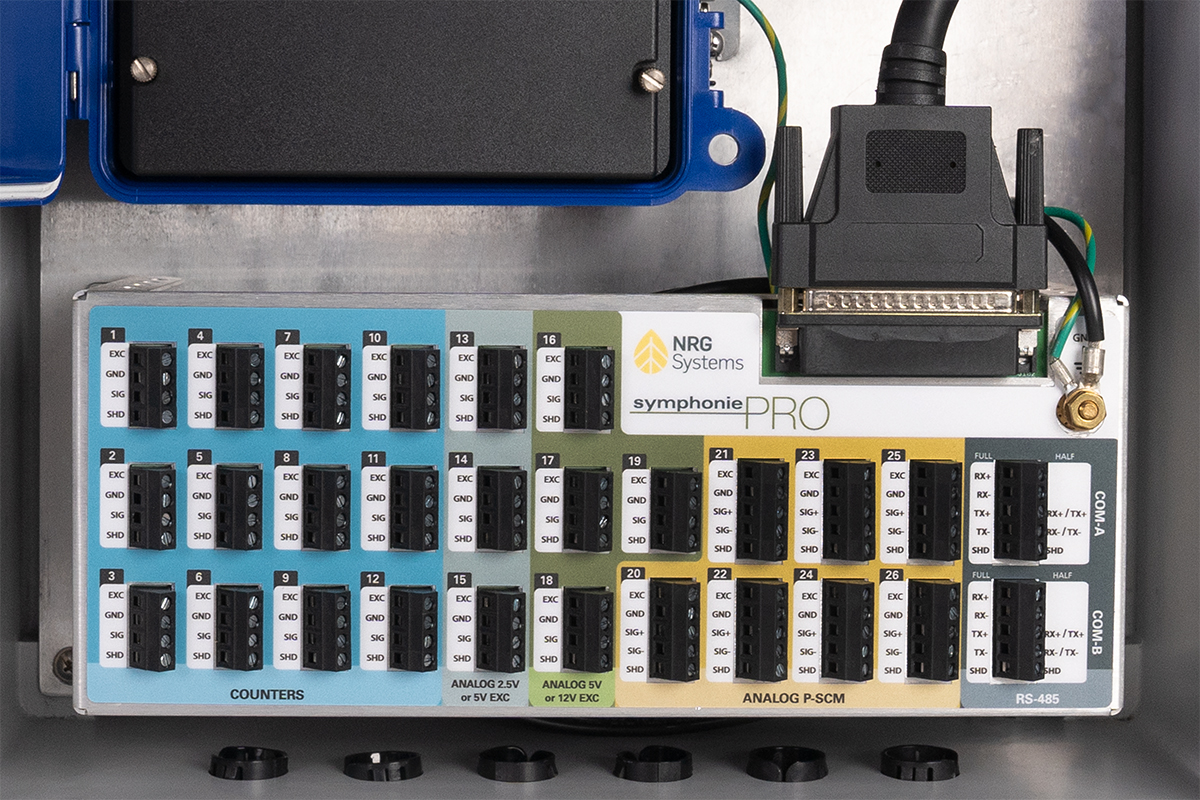
Our wiring panels are designed with the field user in mind. Dedicated terminals for every sensor wire and clear labeling help ensure mistake-free wiring. These input protection devices are required to connect digital and analog sensors to Symphonie® series data loggers. Each wiring panel features channel-by-channel surge protection to shield sensitive data logger circuitry from electrostatic discharge (ESD).
In the event of a lightning strike, the wiring panel will divert the energy to Earth Ground, protecting the data logger from damage. Severe ESD events may require replacement of the wiring panel to restore normal data logging operations.
We recommend carrying a spare wiring panel when performing site visits.
SPECIFICATIONS PRINT SPECS
| SymphoniePRO, 16-Channel (#11178) | SymphoniePRO, 26-Channel (#9294) | SymphoniePLUS3 (#5917) | |
|---|---|---|---|
| DESCRIPTION | |||
| Instrument type | 16 channel wiring panel for SymphoniePRO Data Logger | 26 channel wiring panel for SymphoniePRO Data Logger | 15 channel wiring panel for SymphoniePLUS3 data logger |
| Applications | Wind and solar resource assessment, power performance monitoring, and forecasting | Wind and solar resource assessment, power performance monitoring, and forecasting | Wind resource assessmentTurbine power performance verification |
| Instrument compatibility | SymphoniePRO data logger | SymphoniePRO data logger | SymphoniePLUS3 data logger |
| DATA COLLECTION | |||
| Channel Capacity | Eight (8) counter channelsEight (8) analog channels: Five (5) built-in, Three (3) configurable with signal conditioning modules (P-SCMs) | Twelve (12) counter channelsFourteen (14) analog channels: Seven (7) built-in, Seven (7) configurable with signal conditioning modules (P-SCMs)Two (2) RS-485 communication channels, each full or half duplex with support for up to 6 devices | Six (6) counter channels: Channels 1-3 and 13-15Six (6) analog channels: Channels 7-12 Channels 7-8 dedicated for NRG 200P Wind Direction Vane; Channels 9-12 use analog Signal Conditioning Modules (SCMs) to configure each channel for a particular sensorThree (3) flex channels: Channels 4-6 Analog or counter channel; accepts Signal Conditioning Modules (SCMs) to configure the channel for a particular sensor type |
| Counter Channels Sensor Compatibility | Compatable with a wide array of industry-standard anemometers including:Opto anemometersReed switch anemometersOther frequency signals up to 2,500 Hz | Compatable with a wide array of industry-standard anemometers including:Opto anemometersReed switch anemometersOther frequency signals up to 2,500 Hz | Compatable with a wide array of industry-standard anemometers including:Opto anemometersReed switch anemometersOther frequency signals up to 2,500 Hz |
| Analog Channels Sensor Compatibility | Compatible with a wide array of sensors including:NRG standard analog sensors (200P Wind Direction Vane, 110S Temperature, BP20 Barometric Pressure, RH5X Relative Humidity, etc)Industry-standard pyranometersThree (3) Built-in channels: 0 to 5 V Analog; 2.5 or 5 V excitation; no P-SCMs requiredTwo (2) Built-in channels: 0 to 5 V Analog; 5 or 12 V excitation; no P-SCMs requiredThree (3) P-SCM Channels: signal range dependent on individual P-SCM card | Compatible with a wide array of sensors including:NRG standard analog sensors (200P Wind Direction Vane, 110S Temperature, BP20 Barometric Pressure, RH5X Relative Humidity, etc)Industry-standard pyranometersBuilt-in channels 13-15: 0 to 5 V Analog; 2.5 or 5 V excitation; no P-SCMs requiredBuilt-in channels 16-19: 0 to 5 V Analog; 5 or 12 V excitation; no P-SCMs requiredP-SCM Channels 20-26: signal range dependent on individual P-SCM card | NRG 200P Wind Direction VaneNRG 110S Temperature SensorNRG BP20 Barometric Pressure Sensor (requires optional iPack power)NRG RH5X Relative Humidity Sensor (requires optional iPack power) |
| CONNECTIONS | |||
| Sensor wiring | Sensors connect to wiring panelField wiring panel plugs directly into loggerWiring panel ground stud connects to earth ground with included ground cable | Sensors connected to wiring panelField wiring panel mounted in shelter box connected to logger via interconnect cableGround stud connects to earth ground with includedwith ground cable | Sensors connected to field wiring panelField wiring panel plugs into loggerGround stud connects to earth ground with included ground cable |
| Expansion slots | Three (3) Analog channels configurable with P-SCM signal conditioning modules | Seven (7) signal conditioning module slots accept analog P-SCMsTwo (2) RS-485 serial communication ports on wiring panel | Three (3) SCM slots accept analog or counter SCMsFour (4) SCM slots accept only analog SCMs |
| INSTALLATION | |||
| Mounting | Wiring panel mounts directly to Logger with two screws | Wiring panel mounts separately to shelter box back plate with four (4) Phillips 10-32 x 0.5 in. screws | Wiring panel mounts directly to Logger |
| Tools required | Screwdriver for wiring panel input terminals (included)8mm (5/16 in.) wrench or nut driver for mounting screws and logger ground lug | Screwdriver for wiring panel input terminals (included)8mm (5/16 in.) wrench or nut driver for mounting screws and logger ground lug | Screwdriver for input terminals (included)8mm (5/16 in.) wrench or nut driver for mounting screws and logger ground lug |
| ENVIRONMENTAL | |||
| Operating temperature range | -40 °C to 65 °C (-40 °F to 149 °F) | -40 °C to 65 °C (-40 °F to 149 °F) | -40 °C to 65 °C (-40 °F to 149 °F) |
| Operating humidity range | 0 to 100% relative humidity non-condensingIP65 ingress protection with proper installation in Symphonie shelter box enclosure | 0 to 100% RH non-condensing | 0 to 100% RH non-condensing |
| PHYSICAL | |||
| Weight | .15 Kg (.33 lb) | Wiring Panel: .73 Kg (1.6 lbs)Interconnect Cable: .24 Kg (.52 lb) | .15 Kg (.33 lb) |
| Dimensions | 11.4 cm x 7.6 cm x 5 cm (4.5 in. x 3 in. x 2 in.) | Wiring Panel: 30 cm x 12 cm x 12 cm (11.8 in. x 4.7 in x 4.7 in)Interconnect Cable: 40.6 cm (16 in) | 11.4 cm x 7.6 cm x 5 cm (4.5 in. x 3 in. x 2 in.) |
| MATERIALS | |||
| Wiring panel | Black ABS enclosureZinc-plated screws and terminals | Formed aluminum enclosure, zinc-plated screws and terminals | Fiberglass-epoxy terminal board, sealed gold plated pins, zinc plated screws and terminals |